[TOC]
USB3.0
USB2.0的最大理论传输带宽为480Mb/s(即60MB/s),USB3.0的最大传输带宽则高达5.0Gb/s(500MB/s)。
注意:5Gb/s的带宽并不是5Gb/s除以8得到的625MB/s,而是采用与SATA相同的10位传输模式(在USB2.0的基础上新增了一对纠错码),因此器全速只有500MB/s。
USB3.0引入全双工数据传输,5根线路中两根用来发送数据,另两根用来接收数据,还有一根地线。换句话说,USB3.0可以同步全速地进行读/写操作。以前的USB版本不支持全双工数据传输。
USB3.0控制器FX3电路
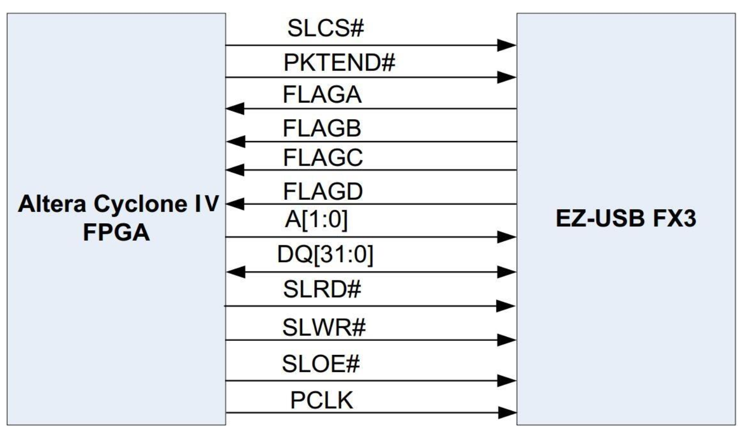
USB3.0控制器FX3与FPGA之间通过SlaveFIFO接口互联,实现大吞吐量数据传输。
fx3_d[31:0]
fx3_a[1:0] (CTL[11]/A CTL[12]/A0)
fx3_clk (PCLK)
fx3_slcs# (CTL[0]/SLCS#)
fx3_slwr# (CTL[1]/SLWR#)
fx3_sloe# (CTL[2]/SLOE#)
fx3_rd# (CTL[3]/SLRD#)
fx3_pktend# (CTL[7]/PKTEND#)
fx3_flaga (CTL[4]/FLAGA)
fx3_flagb (CTL[5]/FLAGB)
fx3_flagc (CTL[8]/GPIO)
fx3_flagd (GTL[9]/GPIO)
复位引脚接上电复位和按键–手动复位。
启动模式:
PMODE[0]
PMODE[1]
PMODE[2]
PMODE[2:0]=F1F I2C启动,如失败,则启用USB引导
PMODE[2:-]=F11 USB引导
USB3.0控制器FX3实例
基于FX3内部DMA的USB传输Loopback实例
Cypress官方提供的固件代码,在 ..\Cypress\EZ-USB FX3 SDK\1.3\fireware\basic_examples\cyfxbulklpautoenum
通过FX3的一对USB Bulk端点实现Loopback的功能。所谓Loopback,通俗地说,就是FX3接收到任何数据,就将其发送出去;从PC端的调试软件看,就是PC给FX3传输什么数据,紧接着就接收到相同的返回数据。
这个Loopback功能的实现过程中,FX3内的ARM9是不参与数据本身的任何传输的,固件配置好后,USB端点之间通过DMA自动实现数据的传输。
基于FX3的UVC传输协议实例
FX3固件SlaveFIFO配置修改说明
功能概述
通过FX3与FPGA之家你的GPIF II接口通信,实现FPGA与FX3之间的数据交互,当然这些数据最终也传输到PC上。换句话说,通过FX3这个“桥梁”,实现FPGA与PC之间USB3.0接口的数据传输。
可以通过Cpyress官方提供的GPIF II Designer工具,获取GPIF II接口的配置参数,然后将这些参数传递给FX3的固件工程中进行编译。
基于FPGA-FX3 Slave FIFO接口的Loopback实例
实现PC端发送数据到FX3,FX3通过知识信号flaga告知FPGA有数据待读取,FPGA端通过SlaveFIFO接口读取PC端发送过来的数据缓存到FPGA内部的FIFO中,FPGA在完成读取操作后,发器一次SlaveFIFO的写入操作,将接收到的数据通过FX3最终返回到PC端。整个数据的收发过程可以在FPGA内部通过在线逻辑分析仪SignalTap II抓取SlaveFIFO接口的所有信号进行查看。
基于FPGA-FX3 Slave FIFO接口的StreamOUT实例
功能概述:
StreamOUT主要功能是PC端发送批量数据到FX3,FX3通过指示信号flaga告知FPGA有数据待读,然后FPGA端通过SlaveFIFO接口读取PC端发送过来的数据缓存到FPGA内部的FIFO中。整个数据的收发过程,在FPGA内部可以通过在线逻辑分析仪SignalTap II抓取SlaveFIFO接口的所有信号进行查看。
【PC】 <==USB3.0==> 【FX3】 <==Slave FIFO==> 【FPGA】
usb_controller模块是SlaveFIFO及其相关功能实现的主要模块。FX3 读/写状态机一旦检测到FX3的SlaveFIFO有可读取的数据,就进入FX3数据读取状态,读取SlaveFIFO中所有的数据,缓存到片内RAM中。
FX3读写状态机简述,上电状态为 FXS_REST,随后就进入 FXS_IDLE状态,判断SlaveFIFO是否有可读取数据,如果有则进入 FXS_READ状态读出FX3的SlaveFIFO中所有的数据,完成后在FXS_RDLY状态稍作延时,接着进入FXS_RSOP状态停留一个时钟周期,最后回到FXS_IDLE状态。
基于FPGA-FX3 Slave FIFO 接口的StreamIN实例
StreamIN主要功能是FPGA端产生批量数据,通过SlaveFIFO接口发送到FX3,直到FX3的多个FIFO通道写满。由于FX3是USB的从机,作为USB主机的PC需要发器读取FX3的待发送数据帧操作,一旦FX3有FIFO空出来,FPGA就再写入新的数据帧。
上电状态为FXS_REST,随后就进入FXS_IDLE状态,判断SlaveFIFO是否为空可以写入数据,如果可以则进入FXS_WRIT状态,写数据到FX3的SlaveFIFO中,接着进入FXS_WSOP状态停留一个时钟周期,最后回到FXS_IDLE状态。
USB_CONTROLLER.v
1
2
3
4
5
6
7
8
9
10
11
12
13
14
15
16
17
18
19
20
21
22
23
24
25
26
27
28
29
30
31
32
33
34
35
36
37
38
39
40
41
42
43
44
45
46
47
48
49
50
51
52
53
54
55
56
57
58
59
60
61
62
63
64
65
66
67
68
69
70
71
72
73
74
75
76
77
78
79
80
81
82
83
84
85
86
87
88
89
90
91
92
93
94
95
96
97
98
99
100
101
102
103
104
105
106
107
108
109
110
111
112
113
114
115
116
117
118
119
120
121
122
123
124
125
126
127
128
129
130
131
132
133
134
135
136
137
138
139
140
141
142
143
144
145
146
147
148
149
150
151
152
153
154
155
156
157
158
159
160
161
162
163
164
165
166
167
168
169
170
171
172
173
174
175
176
177
178
179
180
181
182
183
184
185
186
187
188
189
190
191
192
193
194
195
196
197
198
199
200
201
202
203
204
205
206
207
208
209
210
211
212
213
214
215
216
217
218
219
module usb_controller
(
    input	wire	[ 0: 0]	clk			,	//100MHz? 200MHz? 300MHz? 400MHz?
    input	wire	[ 0: 0]	rst_n		,
    input	wire	[ 0: 0]	fx3_flaga	,	//slave fifo write full when addr 00
    input	wire	[ 0: 0]	fx3_flagb	,	//slave fifo almost write full when addr 00, 6 byte data can be written after this negative
    input	wire	[ 0: 0]	fx3_flagc	,	//slave fifo read empty when addr 11
    input	wire	[ 0: 0]	fx3_flagd	,	//slave fifo read empty almost when addr 11
    output	reg		[ 0: 0]	fx3_pclk	,	//slave fifo sync clock
    output	reg		[ 0: 0]	fx3_slcs_n	,	//slave fifo chip select
    output	reg		[ 0: 0]	fx3_slwr_n	,	//slave fifo write enable
    output	reg		[ 0: 0]	fx3_slrd_n	,	//slave fifo read enable
    output	reg		[ 0: 0]	fx3_sloe_n	,	//slave fifo output enable
    output	reg		[ 0: 0]	fx3_pktend_n,	//package end
    output	reg		[ 1: 0]	fx3_a		,	//
    inout	wire	[31: 0]	fx3_db		,
);
    wire	[ 9: 0]	fifo_used;	//fifo已经使用数据个数
    reg		[ 0: 0]	fifo_rdreq;	//fifo读请求信号,高电平有效
    reg		[ 0: 0]	fx3_dir;	//FX3读写方向指示信号,1--read,0--write
    reg		[ 9: 0]	num;		//数据寄存器
    reg		[ 3: 0]	delaycnt;	//延时计数寄存器
    reg		[ 3: 0]	fxstate;	//状态寄存器
    parameter	FXS_REST	=	4'd0;
    parameter	FXS_IDLE	=	4'd1;
    parameter	FXS_READ	=	4'd2;
    parameter	FXS_RDLY	=	4'd3;
    parameter	FXS_RSOP	=	4'd4;
    parameter	FXS_WRIE	=	4'd5;
    parameter	FXS_WSOP	=	4'd6;

    always @ (posedge clk or negedge rst_n)
        if(!rst_n)
            fx3_dir <= 1'b1;	//read
    	else if(FXS_RSOP == fxstate)
            fx3_dir <= 1'b0;	//write
    	else if(FXS_WSOP == fxstate)
            fx3_dir <= 1'b1;	//read

    //定时读取FX3 FIFO数据并送入FIFO

    //定时读写操作状态机
    always @ (posedge clk or negedge rst_n) begin
        if(!rst_n) begin
            fxstate <= FXS_REST;
        end
    	else begin
            case(fxstate)
            	FXS_REST: begin
                    fxstate <= FXS_IDLE;
                end
                FXS_IDLE: begin
                    if(fx3_flaga)
                        fxstate <= FXS_READ;	//读数据,读取数据个数必须是8-1024
                    else
                        fxstate <= FXS_IDLE;
                end
                FXS_READ: begin
                    if(!fx3_flagb)
                        fxstate <= FXS_RDLY;
                    else
                        fxstate <= FXS_READ;
                end
                FXS_RDLY: begin	//读取flagd拉低后的6个数据
                    if(delaycnt >= 4'd6)
                        fxstate <= FXS_RSOP;
                    else
                        fxstate <= FX_RDLY;
                end
                FXS_RSOP: begin
                	fxstate <= FXS_IDLE;
                end
            default: fxstate <= FXS_IDLE;
            endcase
    	end
    end

    //数据计数器,用于产生读写时序
    always @ (posedge clk or negedge rst_n) begin
        if(!rst_n) begin
        	num <= 10'd0;
        end
        else if(fxstate == FXS_READ) begin
        	num <= num + 1'b1;
        end
        else begin
            num <= 10'd0;
        end
    end

    //6个clock的延时计数器
    always @ (posedge clk or negedge rst_n) begin
        if(!rst_n) begin
        	delaycnt <= 4'd0;
        end
        else if(FXS_RDLY==fxstate)
            delaycnt <= delaycnt + 1'b1;
        else begin
            delaycnt <= 4'd0;
        end
    end

    //FX3 slave fifo控制信号时序产生
    parameter FX3_ON	=	1'b0;
    parameter FX3_OFF	=	1'b1;

    always @ (posedge clk or negedge rst_n) begin
        if(!rst_n) begin
        	fx3_slcs_n	<=	FX3_OFF;
            fx3_slwr_n	<=	FX3_OFF;
            fx3_slrd_n	<=	FX3_OFF;
            fx3_sloe_n	<=	FX3_OFF;
            fx3_pktend_n<=	FX3_OFF;
            fx3_a		<=	2'b11;	//操作FIFO地址
        end
        else if(FXS_IDLE == fxstate) begin
            fx3_slcs_n <= FX3_OFF;
            fx3_slwr_n <= FX3_OFF;
            fx3_slrd_n <= FX3_OFF;
            fx3_sloe_n <= FX3_OFF;
            fx3_pktend_n<=FX3_OFF;
            fx3_a <= 2'b11;
            /*
            if(fx3_dir)
                fx3_a <= 2'b11;//read
            else
                fx3_a <= 2'b00;//write
                */
        end
        else if(FXS_READ == fxstate) begin
        	fx3_slcs_n <= FX3_ON;
            fx3_slwr_n <= FX3_OFF;
            fx3_slrd_n <= FX3_ON;
            fx3_sloe_n <= FX3_ON;
            fx3_pktend_n<=FX3_OFF;
            fx3_a <= 2'b11;
        end
        else if(FXS_RDLY == fxstate) begin
            if(4'd2==delaycnt) begin
            	fx3_slcs_n <= FX3_ON;
                fx3_slwr_n <= FX3_OFF;
                fx3_slrd_n <= FX3_OFF;
                fx3_sloe_n <= FX3_ON;
                fx3_pktend_n<=FX3_OFF;
                fx3_a <= 2'b11;
            end
            else if(delaycnt == 4'd6) begin
            	fx3_slcs_n <= FX3_OFF;
                fx3_slwr_n <= FX3_OFF;
                fx3_slrd_n <= FX3_OFF;
                fx3_sloe_n <= FX3_OFF;
                fx3_pktend_n<= FX3_OFF;
                fx3_a <= 2'b11;
            end
            else begin
            end
        end
        else begin
            fx3_slcs_n <= FX3_OFF;
            fx3_slwr_n <= FX3_OFF;
            fx3_slrd_n <= FX3_OFF;
            fx3_pktend_n<= FX3_OFF;
        end
    end

//slave fifo读操作数据缓存
    reg [31: 0]	fx3_rdb;	//FX3读出数据缓存
    reg	[ 0: 0]	fx3_rdb_en;	//FX3读出数据有效标志位,高电平有效
    wire[31: 0]	fx3_wdb;	//FX3写数据寄存器

    always @ (posedge clk or negedge rst_n) begin
        if(!rst_n) begin
        	fx3_rdb <= 16'd0;
            fx3_rdb_en <= 1'b0;
        end
        else if( (FXS_READ==fxstate) && (10'd4 <= num) ) begin
        	fx3_rdb <= fx3_db;
            fx3_rdb_en <= 1'b1;
        end
        else if( (FXS_RDLY==fxstate) && (4'd5>delaycnt) ) begin
        	fx3_rdb <= fx3_db;
            fx3_rdb_en <= 1'b1;
        end
        else begin
            fx3_rdb <= 16'd0;
            fx3_rdb_en <= 1'b0;
        end
    end
    //assign fx3_db = fx3_dir ? 32'hzzzzzzzz : fx3_wdb;
    assign fx3_db = 32'hzzzzzzzz;

    //RAM缓存FX3读出的数据
    reg	[ 7: 0]	ram_addr;
    always @ (posedge clk or negedge rst_n) begin
        if(!rst_n) begin
        	ram_addr <= 8'd0;
        end
        else if(FXS_IDLE==fxstate) begin
        	ram_addr <= 8'd0;
        end
        else if(fx3_rdb_en)
            ram_addr <= ram_addr + 1'b1;
        else begin

        end
    end

    //RAM例化
    usbrd_ram_debug
    usbrd_ram_debug_inst
    (
        .address	(	ram_addr	)	,
        .clock		(	clk			)	,
        .data		(	{fx3_rdb[7:0], fx3_rdb[15:8], fx3_rdb[23:16], fx3_rdb[31:24]}),
        .wren		(	fx3_rdb_en	)	,
        .q			(				)
    );

endmodule
基于CORDIC的信号发生器
Coordinate Rotation Digital Comuper是CORDIC算法的英文全称,大意是指旋转坐标接近答案。
| i | θi | cosθi | Πcosθi | 1/Πcosθi |
|---|---|---|---|---|
| 0 | 45.0 | 0.7071067812 | 0.7071067812 | 1.414213562 |
| 1 | 26.56505118 | 0.894427191 | 0.632455532 | 1.58113883 |
| 2 | 14.03624347 | 0.9701425001 | 0.6135719911 | 1.629800601 |
| 3 | 7.125016349 | 0.9922778767 | 0.6088339125 | 1.642484066 |
| 4 | 3.576334375 | 0.9980525785 | 0.6076482563 | 1.645688916 |
| 5 | 1.789910608 | 0.9995120761 | 0.6073517701 | 1.646492279 |
| 6 | 0.8951737102 | 0.999877952 | 0.6072776441 | 1.646693254 |
| 7 | 0.4476141709 | 0.9999694838 | 0.6072591123 | 1.646743507 |
| 8 | 0.2238105004 | 0.9999923707 | 0.6072544793 | 1.64675607 |
| 9 | 0.1119056771 | 0.99999980927 | 0.6072533211 | 1.646759211 |
| 10 | 0.05595289189 | 0.99999995232 | 0.6072530315 | 1.646759996 |
| 11 | 0.02797645262 | 0.999999998808 | 0.6072529591 | 1.646760193 |
| 12 | 0.01398822714 | 0.999999999702 | 0.607252941 | 1.646760242 |
| 13 | 0.006994113675 | 0.999999999925 | 0.6072529365 | 1.646760254 |
| 14 | 0.003497056851 | 0.999999999981 | 0.607252935 | 1.646760257 |
| 15 | 0.001748528427 | 0.999999999995 | 0.6072529351 | 1.646760258 |
1
2
3
4
5
6
7
8
9
10
11
12
13
14
15
16
17
18
19
20
21
22
23
24
25
26
27
28
29
30
31
32
33
34
35
36
37
38
39
40
41
42
43
44
45
46
47
48
49
50
51
52
53
#include <studio.h>

double cordic(double angle_para);

int main(void)
{
    double para;

    para = 30.0;
    cordic(para);

    return 0;
}

double cordic(double angle_para)
{
    const double tangent[] = {1.0, 1/2.0, 1/4.0, 1/8.0, 1/16.0, 1/32.0, 1/64.0, 1/128.0, 1/512.0};
    const double angle[] = {45.0, 26.6, 14.0, 7.1, 3.6, 1.8, 0.9, 0.4, 0.2, 0.1 };
    int i, signal;
    double x_cos;
    double y_sin;
    double x_temp;
    double y_temp;
    double z;
    double z_next;

    x_cos = 0.0;
    y_sin = 0.0;
    z = angle_para;
    z_next = 0.0;
    x_temp = 0.6073; // Πcosθi
    y_temp = 0;
    signal = 1;

    for(i=0; i<9; i++)
    {
        x_cos = x_temp - signal*y_temp*tangent[i];
        y_sin = y_temp + signal*x_temp*tangent[i];
        z_next = z - signal*angle[i];

        x_temp = x_cos;
        y_temp = y_sin;
        z = z_next;

        if(z_next>0)
            signal = +1;
        else
            signal = -1;
    }

    return 0;

}
具体操作流程
设置迭代次数为16, 则x0 = 0.607253(Πcosθi,i from 0 to 15),y0 = 0,兵输入待计算得角度θ,θ在[-99.7°, 99.7°]范围内。
根据三个迭代公式进行迭代,i从0到15:
X(i+1) = X(i) - d(i)Y(i)2^(-i)
Y(i+1) = Y(i) + d(i)X(i)2^(-i)
Z(i+1) = Z(i) - d(i)θ(i)
Postscript: Z0=θ,di与Zi同符号。
经过16此迭代计算后,得到的x16和y16分别为cosθ和sinθ。
CORDIC算法的Matlab实现代码如下:
1
2
3
4
5
6
7
8
9
10
11
12
13
14
15
16
17
18
19
20
21
22
23
24
25
26
closeall;
clear;
clc;
%初始化
die = 16; %迭代次数
x = zeros(die+1, 1);
y = zeros(die+1, 1);
z = zeros(die+1, 1);
x(1) = 0.607253; %初始化设置
z(1) = pi/4; %待求角度θ
%迭代操作
for i=1: die
	if z(i) >= 0
		d = 1;
	else
		d = -1;
	end

	x(i+1) = x(i) - d*y(i)*( 2^(-(i-1)) );
	y(i+1) = y(i) + d*x(i)*( 2^(-(i-1)) );
	z(i+1) = z(i) - d*atan( 2^(-(i-1)) );
end

cosa = vpa( x(17), 10 );
sina = vpa( y(17), 10 );
c = vpa( z(17), 10);
FPGA有很多加速计算的方法,例如乒乓操作、流水线操作等。
CORDIC算法适合使用16级流水线。
为了避免浮点运算,为了满足精度要求,对每个变量都放大了2^16倍,并且引入了有符号型reg和算数右移。
1
2
3
4
5
6
7
8
9
10
11
12
13
14
15
16
17
18
19
20
21
22
23
24
25
26
27
28
29
30
31
32
33
34
35
36
37
38
39
40
41
42
43
44
45
46
47
48
49
50
51
52
53
54
55
56
57
58
59
60
61
62
63
64
65
66
67
68
69
70
71
72
73
74
75
76
77
78
79
80
81
82
83
84
85
86
87
88
89
90
91
92
93
94
95
96
97
98
99
100
101
102
103
104
105
106
107
108
109
110
111
112
113
114
115
116
117
118
119
120
121
122
123
124
125
126
127
128
129
130
131
132
133
134
135
136
137
138
139
140
141
142
143
144
145
146
147
148
149
150
151
152
153
154
155
156
157
158
159
160
161
162
163
164
165
166
167
168
169
170
171
172
173
174
175
176
177
178
179
180
181
182
183
184
185
186
187
188
189
190
191
192
193
194
195
196
197
198
199
200
201
202
203
204
205
206
207
208
209
210
211
212
213
214
215
216
217
218
219
220
221
222
223
224
225
226
227
228
229
230
231
232
233
234
235
236
237
238
239
240
241
242
243
244
245
246
247
248
249
250
251
252
253
254
255
256
257
258
259
260
261
262
263
264
265
266
267
268
269
270
271
272
273
274
275
276
277
278
279
280
281
282
283
284
285
286
287
288
289
290
291
292
293
294
295
296
297
298
299
300
301
302
303
304
305
306
307
308
309
310
311
312
313
314
315
316
317
318
319
320
321
322
323
324
325
326
327
328
329
330
331
332
333
334
335
336
337
338
339
340
341
342
343
344
345
346
347
348
349
350
351
352
353
354
355
356
357
358
359
360
361
362
363
364
365
366
367
368
369
370
371
372
373
374
375
376
377
378
379
380
381
382
383
384
385
386
387
388
389
390
391
392
393
394
395
396
397
398
399
400
401
402
403
404
405
406
407
408
409
410
411
412
413
414
415
416
417
418
419
420
421
422
423
424
425
426
427
428
429
430
module cordic#(
	parameter pipeline = 16;
    parameter k = 32'h09b74;	//k = 0.607253*2^16, 32'h09b74
)
(
    input	wire			[ 0: 0]	clk_50MHz	,
    input	wire			[ 0: 0]	rst_n		,
    input	wire			[31: 0]	phase		,
    output	reg		signed	[31: 0]	sin			,
    output	wire	signed	[31: 0]	cos			,
    output	wire	signed	[31: 0]	error
);
	`define	rot0  32'd2949120    	//45*2^16
	`define	rot1  32'd1740992    	//26.5651*2^16
	`define rot2  32'd919872    	//14.0362*2^16
	`define rot3  32'd466944    	//7.1250*2^16
	`define rot4  32'd234368    	//3.5763*2^16
	`define rot5  32'd117312    	//1.7899*2^16
	`define rot6  32'd58688    		//0.8952*2^16
	`define rot7  32'd29312    		//0.4476*2^16
	`define rot8  32'd14656    		//0.2238*2^16
	`define rot9  32'd7360    		//0.1119*2^16
	`define rot10 32'd3648    		//0.0560*2^16
	`define rot11 32'd1856			//0.0280*2^16
	`define rot12 32'd896    		//0.0140*2^16
	`define rot13 32'd448    		//0.0070*2^16
	`define rot14 32'd256    		//0.0035*2^16
	`define rot15 32'd128    		//0.0018s*2^16

    reg signed	[31: 0]	x0 = 0, y0 = 0, z0 = 0;
    reg	signed	[31: 0]	x1 = 0, y1 = 0, z1 = 0;
    reg	signed	[31: 0]	x2 = 0, y2 = 0, z2 = 0;
    reg	signed	[31: 0]	x3 = 0, y3 = 0, z3 = 0;
    reg	signed	[31: 0]	x4 = 0, y4 = 0, z4 = 0;
    reg	signed	[31: 0]	x5 = 0, y5 = 0, z5 = 0;
    reg	signed	[31: 0]	x6 = 0, y6 = 0, z6 = 0;
    reg	signed	[31: 0]	x7 = 0, y7 = 0, z7 = 0;
    reg	signed	[31: 0]	x8 = 0, y8 = 0, z8 = 0;
    reg	signed	[31: 0]	x9 = 0, y9 = 0, z9 = 0;
    reg	signed	[31: 0]	x10 = 0, y10 = 0, z10 = 0;
    reg	signed	[31: 0]	x11 = 0, y11 = 0, z11 = 0;
    reg	signed	[31: 0]	x12 = 0, y12 = 0, z12 = 0;
    reg	signed	[31: 0]	x13 = 0, y13 = 0, z13 = 0;
    reg	signed	[31: 0]	x14 = 0, y14 = 0, z14 = 0;
    reg	signed	[31: 0]	x15 = 0, y15 = 0, z15 = 0;
    reg	signed	[31: 0]	x16 = 0, y16 = 0, z16 = 0;
    reg	[ 1: 0]	quadrant[pipeline: 0];

    always @ (posedge clk_50MHz or negedge rst_n) begin
        if(!rst_n) begin
        	x0 <= 1'b0;
            y0 <= 1'b0;
            z0 <= 1'b0;
        end
        else begin
            x0 <= k;
            y0 <= 32'd0;
            z0 <= Phase[15: 0]<<16;
        end
    end

    always @ (posedge clk_50MHz or negedge rst_n) begin
        if(!rst_n) begin
        	x1 <= 1'b0;
            y1 <= 1'b0;
            z1 <= 1'b0;
        end
        else if(z0[31]) begin
            x1 <= x0 + y0;
        	y1 <= y0 - x0;
            z1 <= z0 + `rot0;
        end
        else begin
			x1 <= x0 - y0;
        	y1 <= y0 + x0;
            z1 <= z0 - `rot0;
        end
    end


    always @ (posedge clk_50MHz or negedge rst_n) begin
        if(!rst_n) begin
        	x2 <= 1'b0;
            y2 <= 1'b0;
            z2 <= 1'b0;
        end
        else if(z1[31]) begin
            x2 <= x1 + (y1 >>> 1);
            y2 <= y1 - (x1 >>> 1);
            z2 <= z1 + `rot1;
        end
        else begin
            x2 <= x1 - (y1 >>> 1);
            y2 <= y1 + (x1 >>> 1);
            z2 <= z1 - `rot1;
        end
    end

    always @ (posedge clk_50MHz or negedge rst_n) begin
        if(!rst_n) begin
        	x3 <= 1'b0;
            y3 <= 1'b0;
            z3 <= 1'b0;
        end
        else if(z2[31]) begin
            x3 <= x2 + (y2 >>> 2);
            y3 <= y2 - (x2 >>> 2);
            z3 <= z2 + `rot2;
        end
        else begin
            x3 <= x2 - (y2 >>> 2);
            y3 <= y2 + (x2 >>> 2);
            z3 <= z2 - `rot2;
        end
    end

    always @ (posedge clk_50MHz or negedge rst_n) begin
        if(!rst_n) begin
            x4 <= 1'b0;
            y4 <= 1'b0;
            z4 <= 1'b0;
        end
        else if(z3[31]) begin
            x4 <= x3 + (y3 >>> 3);
            y4 <= y3 - (x3 >>> 3);
            z4 <= z3 + `rot3;
        end
        else begin
            x4 <= x3 - (y3 >>> 3);
            y4 <= y3 + (x3 >>> 3);
            z4 <= z3 - `rot3;
        end
    end

    always @ (posedge clk_50MHz or negedge rst_n) begin
        if(!rst_n) begin
        	x5 <= 1'b0;
            y5 <= 1'b0;
            z5 <= 1'b0;
        end
        else if(z4[31]) begin
            x5 <= x4 + (y4 >>> 4);
            y5 <= y4 - (x4 >>> 4);
            z5 <= z4 + `rot4;
        end
        else begin
            x5 <= x4 - (y4 >>> 4);
            y5 <= y4 + (x4 >>> 4);
            z5 <= z4 - `rot4;
        end
    end

    always @ (posedge clk_50MHz or negedge rst_n) begin
        if(!rst_n) begin
        	x6 <= 1'b0;
            y6 <= 1'b0;
            z6 <= 1'b0;
        end
        else if(z5[31]) begin
            x6 <= x5 + (y5 >>> 5);
            y6 <= y5 - (x5 >>> 5);
            z6 <= z5 + `rot5;
        end
        else begin
            x6 <= x5 - (y5 >>> 5);
            y6 <= y5 + (x5 >>> 5);
            z6 <= z5 - `rot5;
        end
    end

    always @ (posedge clk_50MHz or negedge rst_n) begin
        if(!rst_n) begin
        	x7 <= 1'b0;
            y7 <= 1'b0;
            z7 <= 1'b0;
        end
        else if(z6[31]) begin
            x7 <= x6 + (y6 >>> 6);
            y7 <= y6 - (x6 >>> 6);
            z7 <= z6 + `rot6;
        end
        else begin
            x7 <= x6 - (y6 >>> 6);
            y7 <= y6 + (x6 >>> 6);
            z7 <= z6 - `rot6;
        end
    end

    always @ (posedge clk_50MHz or negedge rst_n) begin
        if(!rst_n) begin
        	x8 <= 1'b0;
            y8 <= 1'b0;
            z8 <= 1'b0;
        end
        else if(z7[31]) begin
            x8 <= x7 + (y7 >>> 7);
            y8 <= y7 - (x7 >>> 7);
            z8 <= z7 + `rot7;
        end
        else begin
            x8 <= x7 - (y7 >>> 7);
            y8 <= y7 + (x7 >>> 7);
            z8 <= z7 - `rot7;
        end
    end

    always @ (posedge clk_50MHz or negedge rst_n) begin
        if(!rst_n) begin
        	x9 <= 1'b0;
            y9 <= 1'b0;
            z9 <= 1'b0;
        end
        else if(z8[31]) begin
            x9 <= x8 + (y8 >>> 8);
            y9 <= y8 - (x8 >>> 8);
            z9 <= z8 + `rot8;
        end
        else begin
            x9 <= x8 - (y8 >>> 8);
            y9 <= y8 + (x8 >>> 8);
            z9 <= z8 - `rot8;
        end
    end

    always @ (posedge clk_50MHz or negedge rst_n) begin
        if(!rst_n) begin
        	x10 <= 1'b0;
            y10 <= 1'b0;
            z10 <= 1'b0;
        end
        else if(z9[31]) begin
            x10 <= x9 + (y9 >>> 9);
            y10 <= y9 - (x9 >>> 9);
            z10 <= z9 + `rot9;
        end
        else begin
            x10 <= x9 - (y9 >>> 9);
            y10 <= y9 + (x9 >>> 9);
            z10 <= z9 - `rot9;
        end
    end

     always @ (posedge clk_50MHz or negedge rst_n) begin
        if(!rst_n) begin
        	x11 <= 1'b0;
            y11 <= 1'b0;
            z11 <= 1'b0;
        end
        else if(z10[31]) begin
            x11 <= x10 + (y10 >>> 10);
            y11 <= y10 - (x10 >>> 10);
            z11 <= z10 + `rot10;
        end
        else begin
            x11 <= x10 - (y10 >>> 10);
            y11 <= y10 + (x10 >>> 10);
            z11 <= z10 - `rot10;
        end
    end

     always @ (posedge clk_50MHz or negedge rst_n) begin
        if(!rst_n) begin
        	x12 <= 1'b0;
            y12 <= 1'b0;
            z12 <= 1'b0;
        end
        else if(z11[31]) begin
            x12 <= x11 + (y >>> 11);
            y12 <= y11 - (x >>> 11);
            z12 <= z11 + `rot11;
        end
        else begin
            x12 <= x11 - (y >>> 11);
            y12 <= y11 + (x >>> 11);
            z12 <= z11 - `rot11;
        end
    end

     always @ (posedge clk_50MHz or negedge rst_n) begin
        if(!rst_n) begin
        	x13 <= 1'b0;
            y13 <= 1'b0;
            z13 <= 1'b0;
        end
        else if(z12[31]) begin
            x13 <= x12 + (y >>> 12);
            y13 <= y12 - (x >>> 12);
            z13 <= z12 + `rot12;
        end
        else begin
            x13 <= x12 - (y >>> 12);
            y13 <= y12 + (x >>> 12);
            z13 <= z12 - `rot12;
        end
    end

     always @ (posedge clk_50MHz or negedge rst_n) begin
        if(!rst_n) begin
        	x14 <= 1'b0;
            y14 <= 1'b0;
            z14 <= 1'b0;
        end
         else if(z13[31]) begin
            x14 <= x13 + (y >>> 13);
            y14 <= y13 - (x >>> 13);
            z14 <= z13 + `rot13;
        end
        else begin
            x14 <= x13 - (y >>> 13);
            y14 <= y13 + (x >>> 13);
            z14 <= z13 - `rot13;
        end
    end

     always @ (posedge clk_50MHz or negedge rst_n) begin
        if(!rst_n) begin
        	x15 <= 1'b0;
            y15 <= 1'b0;
            z15 <= 1'b0;
        end
         else if(z14[31]) begin
            x15 <= x14 + (y >>> 14);
            y15 <= y14 - (x >>> 14);
            z15 <= z14 + `rot14;
        end
        else begin
            x15 <= x14 - (y >>> 14);
            y15 <= y14 + (x >>> 14);
            z15 <= z14 - `rot14;
        end
    end

     always @ (posedge clk_50MHz or negedge rst_n) begin
        if(!rst_n) begin
        	x16 <= 1'b0;
            y16 <= 1'b0;
            z16 <= 1'b0;
        end
         else if(z15[31]) begin
            x16 <= x15 + (y >>> 15);
            y16 <= y15 - (x >>> 15);
            z16 <= z15 + `rot15;
        end
        else begin
            x16 <= x15 - (y >>> 15);
            y16 <= y15 + (x >>> 15);
            z16 <= z15 - `rot15;
        end
    end


    always @ (posedge clk_50MHz or negedge rst_n) begin
        if(!rst_n) begin
            quadrant[0]		<=	1'b0;
            quadrant[1]		<=	1'b0;
            quadrant[2]		<=	1'b0;
            quadrant[3]		<=	1'b0;
            quadrant[4]		<=	1'b0;
            quadrant[5]		<=	1'b0;
            quadrant[6]		<=	1'b0;
            quadrant[7]		<=	1'b0;
            quadrant[8]		<=	1'b0;
            quadrant[9]		<=	1'b0;
            quadrant[10]	<=	1'b0;
            quadrant[11]	<=	1'b0;
            quadrant[12]	<=	1'b0;
            quadrant[13]	<=	1'b0;
            quadrant[14]	<=	1'b0;
            quadrant[15]	<=	1'b0;
            quadrant[16]	<=	1'b0;
        end
        else begin
            quadrant[0] <= phase[17:16];
            quadrant[1] <= quadrant[0];
            quadrant[2] <= quadrant[1];
            quadrant[3] <= quadrant[2];
            quadrant[4] <= quadrant[3];
            quadrant[5] <= quadrant[4];
            quadrant[6] <= quadrant[5];
            quadrant[7] <= quadrant[6];
            quadrant[8] <= quadrant[7];
            quadrant[9] <= quadrant[8];
            quadrant[10] <= quadrant[9];
            quadrant[11] <= quadrant[10];
            quadrant[12] <= quadrant[11];
            quadrant[13] <= quadrant[12];
            quadrant[14] <= quadrant[13];
            quadrant[15] <= quadrant[14];
            quadrant[16] <= quadrant[15];
        end
    end

    always @ (posedge clk_50MHz or negedge rst_n) begin
        if(!rst_n) begin
        	cos <= 1'b0;
            sin <= 1'b0;
            error<= 1'b0;
        end
        else begin
            error <= z16;
            case(quadrant[16])
                //if the phase is in first quadrant,the sin(x)=sin(a), cos(x)=cos(a)
                2'b00: begin
                	cos <= x16;
                    sin <= y16;
                end
                //if the phase is in second quadrant,the sin(x)=sin(a+90)=cos(a), cos(x) = cos(a+90)=-sin(a)
                2'b01: begin
                    cos <= ~(y16) + 1'b1;	//-sin
                    sin <= x16;
                end
                //if the phase is in third quadrant, the sin(x)=sin(a+180)=-sin(a), cos(x)=cos(a+180)=-cos(a)
                2'b10: begin
                    cos <= ~(x16) + 1'b1;	//-cos
                    sin <= x16;				//-sin
                end
                //if the phase is in forth quadrant, the sinx(x)=sin(a+270)=-cos(A), cos(x) = cos(a+270)=sin(a)
                2'b11: begin
                    cos <= y16;				//sin
                    sin <= ~(x16) + 1'b1;	//-cos
                end
                default: begin
                end
            endcase
        end
    end


endmodule
仿真代码Testbench:
1
2
3
4
5
6
7
8
9
10
11
12
13
14
15
16
17
18
19
20
21
22
23
24
25
26
27
28
29
30
31
32
33
34
35
36
37
38
39
40
41
42
43
44
45
46
47
48
49
50
51
52
53
54
55
56
57
58
59
60
61
62
63
64
65
66
67
68
69
70
71
72
73
74
75
76
77
78
79
`timescale 1ps/1ps

module Cordic_tb;
    //input
    reg		[ 0: 0]	clk_50MHz	;
    reg		[ 0: 0]	rst_n		;
    reg		[15: 0]	cnt			;
    reg		[15: 0]	cnt_n		;
    reg		[31: 0]	Phase		;
    reg		[31: 0]	Phase_n		;
    wire	[31: 0]	Sin			;
    wire	[31: 0]	Cos			;
    wire	[31: 0]	Error		;

    //
    COrdic uut
    (
        .clk_50MHz	(	clk_50MHz	),
        .rst_n		(	rst_n		),
        .Phase		(	Phase		),
        .Sin		(	Sin			),
        .Cos		(	Cos			),
        .Error		(	Error		)
    );

    initial
    begin
    	#0
        	clk_50MHz = 1'b0;
        #10000
        	rst_n = 1'b0;
        #10000
        	rst_n = 1'b1;
        #10000000
        	$stop;
    end

    always #10000
    begin
    	clk_50MHz = ~clk_50MHz;
    end

    always @ (posedge clk_50MHz or negedge rst_n)
    begin
        if(!rst_n)
            cnt <= 1'b0;
        else
            cnt <= cnt_n;
    end

    always @ (*)
    begin
        if(16'd359)
            cnt_n = 1'b0;
        else
            cnt_n = cnt + 1'b1;
    end

    //生成相位,Phase[17:16]为相位的象限,Phase[15:0]为相位的值
    always @ (posedge clk_50MHz or negedge rst_n)
    begin
        if(!rst_n)
            Phase <= 1'b0;
        else
            Phase <= Phase_n;
    end

    always@(*)
    begin
       if(cnt <=16'd90)
          Phase_n = cnt;
       elseif(cnt >16'd90&& cnt <=16'd180)
          Phase_n ={2'd01,cnt -16'd90};
       elseif(cnt >16'd180&& cnt <=16'd270)
          Phase_n ={2'd10,cnt -16'd180};
       elseif(cnt >16'd270)
          Phase_n ={2'd11,cnt -16'd270};
    end
endmodule
基于Shane’s硬件同步从设置FIFO接口实例
FPGA通过同步从设备FIFO接口连接至USB3.0芯片CYUSB3014。
固件和软件组件
用到的固件和软件组件主要包括以下内容:
- FX3同步从设备FIFO固件(firmwave)
- Control Center和Streamer软件工具
下图显示了FPGA和FX3之间的互联概念图:
该实例包括以下部分:
- 回送传输:FPGA先从FX3读取整个缓冲区的内容,然后将其写会到FX3内。USB主机应该发送 OUT/IN 令牌数据包,用于发送和接收该数据。可以使用Control Center工具实现该操作。
- 短数据包:FPGA先将一个完整的数据包传送到FX3,然后再发送一个短数据包。USB主机应该发送IN令牌数据包,用于接收该数据。
- 零长度数据包(ZLP)传输:FPGA先将一个完整的数据包传输到FX3,然后在发送一个零长度数据包。USB主机应该发送IN令牌数据包,用于接收该数据。
- 串流(IN)数据传输:FPGA实现单向传输,即是通过同步从设备FIFO连续将数据写入到FX3。USB主机应该发送IN令牌数据包,用于接收该数据。
- 串流(OUT)数据传输:FPGA实现单向传输,即是通过同步从设备FIFO从FX3连续读取数据。USB主机应该发送OUT令牌数据包,用于发送该数据。
FPGA实现的详细信息
使用Altera Cyclone IV(EP4CE40F23I7N) +CYUSB3014的电路实现。
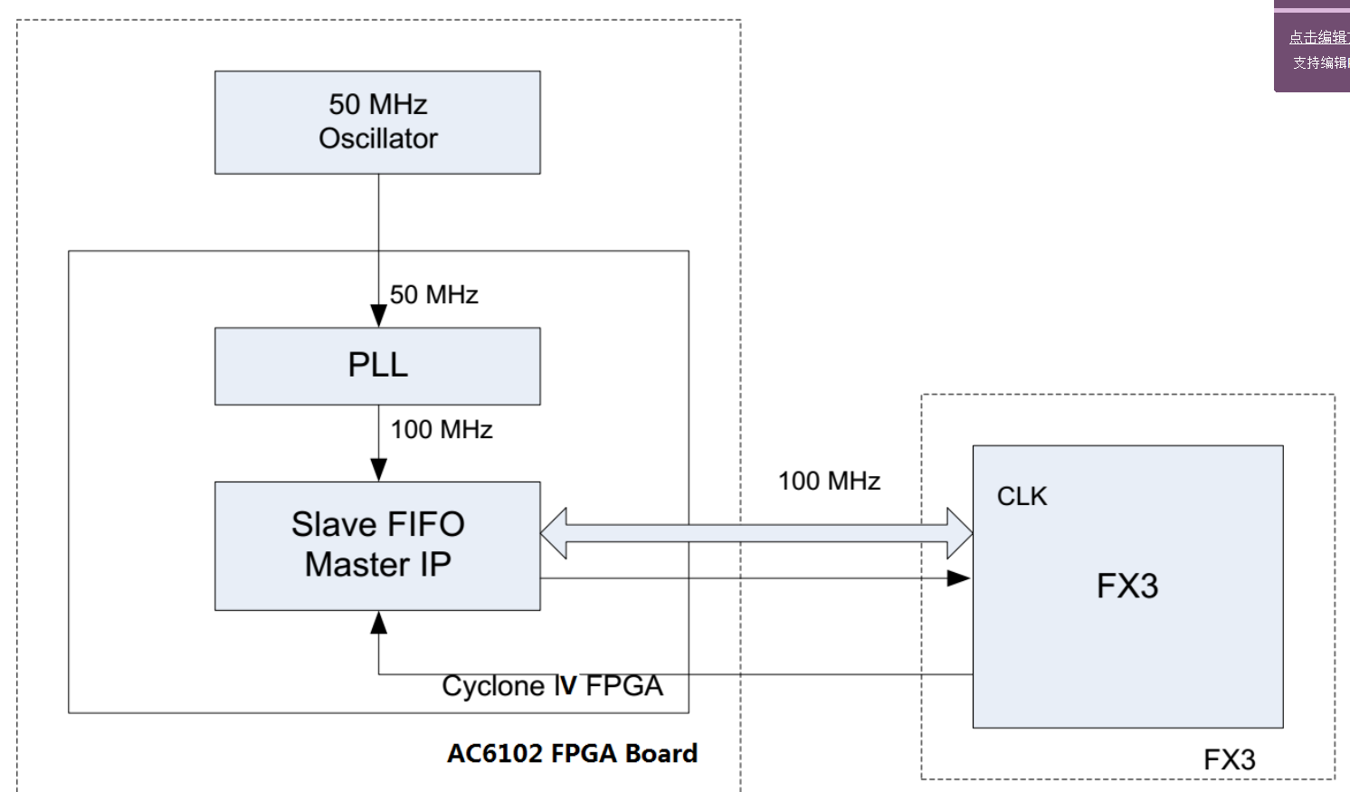
为了得到FX3的最大性能,CPIF II接口将以100MHz的频率工作。本硬件外部配置了50MHz的有源晶振。FPGA内部使用PLL,从50MHz外部时钟生成一个100MHz的时钟。
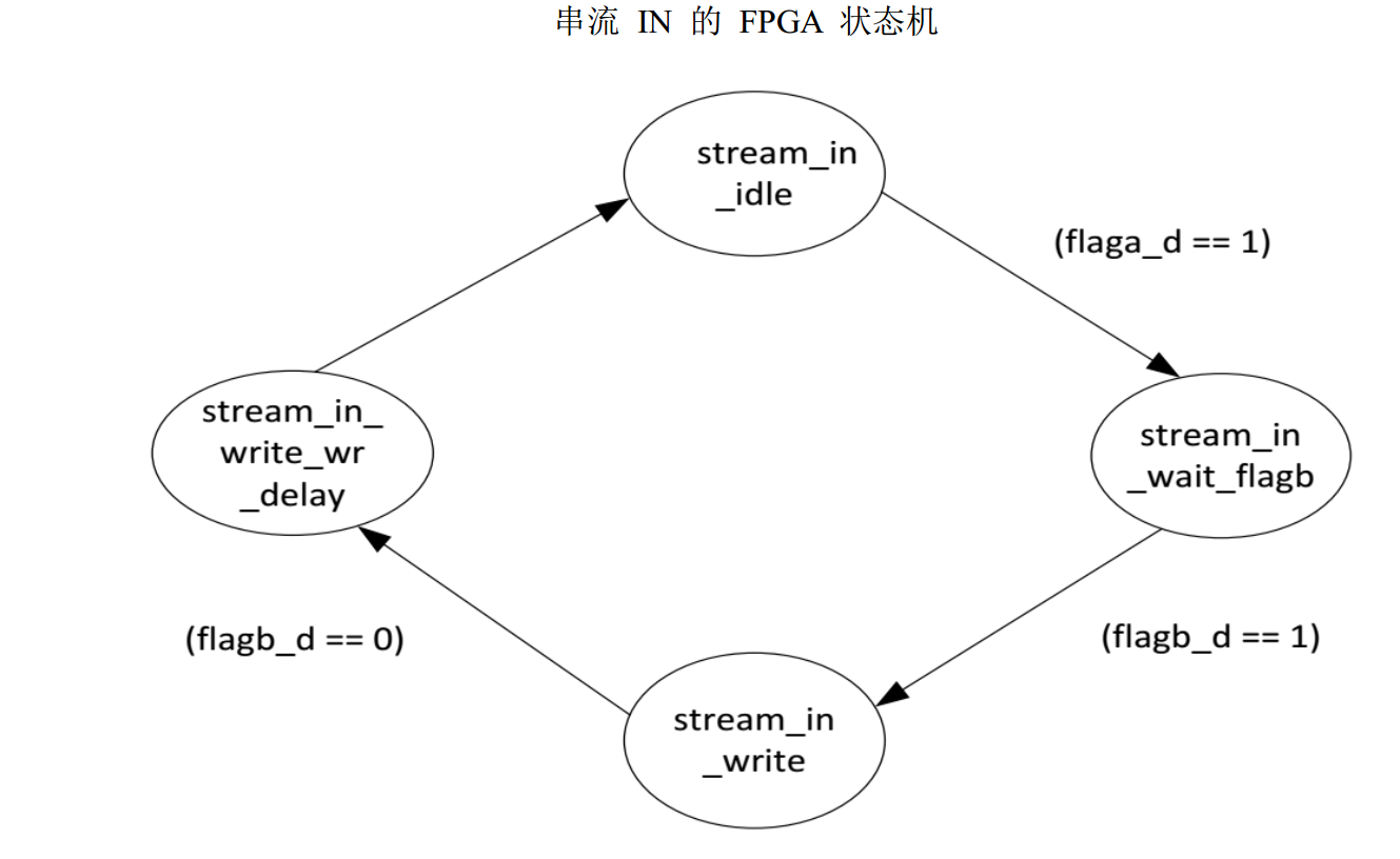
串流IN实例(FPGA对从设备FIFO进行写操作)
下图显示了Verilog RTL中针对串流IN传输执行的状态机。
-
stream_in_idle状态:
该状态用于初始化状态机中所使用的所有寄存器和信号。
从设备FIFO控制线的状态为:
PKTEND# = 1; SLOE# = 1; SLRD# = 1; SLCS# = 0; SLWR# = 1; A[1:0];
-
stream_in_wait_flagb状态:
每当flaga_d = 1时,状态机将进入该状态,并等待flagb_d。
-
stream_in_write状态:
每当flagb_d = 1时,状态机进入该状态,并开始写入从设备FIFO接口。从设备FIFO控制线的状态为:
PKTEND# = 1; SLOE# = 1; SLRD# = 1; SLCS# = 0; SLWR# = 0; A[1:0] = 0;
-
stream_in_write_wr_delay状态:
每当flagb_d = 0时,状态机将进入该状态。从设备FIFO控制线的状态为:
PKETEND# = 1; SLOE# = 1; SLRD# = 1; SLCS# = 0; SLWR# = 1; A[1:0] = 0;
经过一个时钟周期后,状态机将进入stream_in_idle状态,根据使用局部标值情况下的通用公式,局部标志flagb变为0后,FX3需要对处于激活状态的SLWR#进行采样两个周期。由于考虑到FPGA至接口哦的一个周期的传输延迟,FPGA再对被置为0的flagb_d(flagb的出发输出)进行采样后激活SLWR#一个周期。
1
2
3
4
5
6
7
8
9
10
11
12
13
14
15
16
17
18
19
20
21
22
23
24
25
26
27
28
29
30
31
32
33
34
35
36
37
38
39
40
41
42
43
44
45
46
47
48
49
50
51
52
53
54
55
56
57
58
59
60
61
62
63
64
65
66
67
68
69
70
71
72
73
74
75
76
77
78
79
80
81
82
83
84
85
86
87
88
89
90
91
92
93
94
95
96
97
98
99
100
101
102
103
104
105
106
107
108
109
110
111
112
113
114
115
116
117
118
119
120
121
122
123
124
125
126
127
128
129
130
131
132
133
134
135
136
137
138
139
140
141
142
143
144
145
146
147
148
149
150
151
152
153
module slaveFIFO2b_streamIN(
	input  reset_in_,            //input reset active low
	input  clk,                  //input clp 50 Mhz
	inout  [31:0]fdata,          //data bus
	output [1:0]faddr,           //output fifo address
	output slrd,                 //output read select
	output slwr,                 //output write select
	input  flaga,                //full flag
	input  flagb,                //partial full flag
      	input  flagc,                //empty flag
	input  flagd,                //empty partial flag
	output sloe,                 //output output enable select
	output clk_out,              //output clk 100 Mhz and 180 phase shift
	output slcs,                 //output chip select
	output pktend,               //output pkt end
	output [1:0]PMODE,
	output RESET
//	output PMODE_2               //used for debugging
);


reg [2:0]current_stream_in_state;
reg [2:0]next_stream_in_state;
reg [31:0]data_gen_stream_in;

//parameters for StreamIN mode state machine
parameter [2:0] stream_in_idle                    = 3'd0;
parameter [2:0] stream_in_wait_flagb              = 3'd1;
parameter [2:0] stream_in_write                   = 3'd2;
parameter [2:0] stream_in_write_wr_delay          = 3'd3;


reg  flaga_d;
reg  flagb_d;
reg  flagc_d;
reg  flagd_d;


//output signal assignment
assign slrd   = 1'b1;
assign slwr   = slwr_streamIN_d1_;
assign faddr  = 2'd0;
assign sloe   = 1'b1;
assign fdata  = (slwr_streamIN_d1_) ? 32'dz : data_gen_stream_in;
assign PMODE  = 2'b11;
assign RESET  = 1'b1;
assign slcs   = 1'b0;
assign pktend = 1'b1;

wire clk_100;
wire lock;
wire reset_;

//clock generation(pll instantiation)
pll inst_clk_pll
	(
		.areset(1'b0/*reset2pll*/),
		.inclk0(clk),
		.c0(clk_100),
		.locked(lock)
	);


//ddr is used to send out the clk(ODDR2 instantiation)
//
ddr inst_ddr_to_send_clk_to_fx3
        (
	.datain_h(1'b0),
	.datain_l(1'b1),
	.outclock(clk_100),
	.dataout(clk_out)
	);

assign reset_ = lock;

///flopping the INPUTs flags
always @(posedge clk_100, negedge reset_)begin
	if(!reset_)begin
		flaga_d <= 1'd0;
		flagb_d <= 1'd0;
		flagc_d <= 1'd0;
		flagd_d <= 1'd0;
	end else begin
		flaga_d <= flaga;
		flagb_d <= flagb;
		flagc_d <= flagc;
		flagd_d <= flagd;
	end
end

assign slwr_streamIN_ = ((current_stream_in_state == stream_in_write)) ? 1'b0 : 1'b1;

reg slwr_streamIN_d1_;
always @(posedge clk_100, negedge reset_)begin
	if(!reset_)begin
		slwr_streamIN_d1_ <= 1'b1;
	end else begin
		slwr_streamIN_d1_ <= slwr_streamIN_;
	end
end


//streamIN mode state machine
always @(posedge clk_100, negedge reset_)begin
	if(!reset_)begin
		current_stream_in_state <= stream_in_idle;
	end else begin
		current_stream_in_state <= next_stream_in_state;
	end
end

//StreamIN mode state machine combo
always @(*)begin
	next_stream_in_state = current_stream_in_state;
	case(current_stream_in_state)
	stream_in_idle:begin
		if(flaga_d == 1'b1)begin
			next_stream_in_state = stream_in_wait_flagb;
		end else begin
			next_stream_in_state = stream_in_idle;
		end
	end
	stream_in_wait_flagb :begin
		if (flagb_d == 1'b1)begin
			next_stream_in_state = stream_in_write;
		end else begin
			next_stream_in_state = stream_in_wait_flagb;
		end
	end
	stream_in_write:begin
		if(flagb_d == 1'b0)begin
			next_stream_in_state = stream_in_write_wr_delay;
		end else begin
		 	next_stream_in_state = stream_in_write;
		end
	end
        stream_in_write_wr_delay:begin
			next_stream_in_state = stream_in_idle;
	end
	endcase
end

//data generator counter for StreamIN modes
always @(posedge clk_100, negedge reset_)begin
	if(!reset_)begin
		data_gen_stream_in <= 32'd0;
	end else if(slwr_streamIN_d1_ == 1'b0) begin
		data_gen_stream_in <= data_gen_stream_in + 1;
	end
end


endmodule